
COMPUTERBOARDS
INSTALLATION INSTRUCTIONS
FOR USING THE
PCI-1200/JR WITH
THE ARIEL
PERFORMANCE ANALYSIS SYSTEM
January 1999
The
PCI-DAS1200 series boards are easy to use.
This quick start procedure will help you setup, install and test
your board quickly and easily. For
additional information, see the ComputerBoard web site:
www.computerboards.com.
Hardware Installation
1.
Shut
down
and turn off your computer. Disconnect
the power cord and remove the computer cover.
2.
Locate
vacant slot:
Locate any vacant PCI expansion slot and remove the expansion slot screw
and cover. Save the screw
for step #4 below.
3.
Unpack
the PCI-1200/JR card:
Caution.
Touch a grounded metal object to discharge any build-up
of static electricity before handling the 1200/JR card.
Handle the card by its edges.
If you lay it down, place it on the static-proof bag it is
shipped in.
4.
Install
the ComputerBoards card:
Push the 1200/JR card FIRMLY into the PCI slot and replace the
PCI slot cover screw.
5.
Replace
computer cover:
Replace the screws that hold the cover in place.
6.
Reconnect
the power
to the back of your computer and start your system.
Windows 95/98 will automatically detect the board as it starts
up.
Install
the InstaCAL Software
1.
Insert
the InstaCAL disk or CD into an appropriate disk drive in your computer.
2.
Select
Start Menu
located in the lower left corner of the screen. Select
RUN and then BROWSE. Select
the drive where the InstaCal disk or CD resides.
Select SETUP.EXE and then OK.
The install wizard will
now launch, and you will then be prompted for additional information.
Follow the instructions and, if possible, accept the defaults.
Welcome Menu:
Next
Install Type:
32-Bit Instacal
Select Location:
C:\CB\
Create Program Folder
Computerboards
Install Disk 2
Install Disk 3
Modify Autoexec.bat
Yes
Old File Saved as autoexec.bak
Install CBClient:
No
Modify system.ini
Yes
Old File Save as system.bak
View Readme file:
Yes
Restart Computer:
Yes
The installation
routines will create all required folders/directories and unpack the
various pieces of compressed software.
The default location is on your main hard drive in a directory or
folder named (C:\CB\).
Launching/Using the InstaCal Software
1.
Run the InstaCal software:
Start your computer. From
the Windows 95/98 main screen, select Start, PROGRAMS, COMPUTERBOARDS
and then INSTACAL.
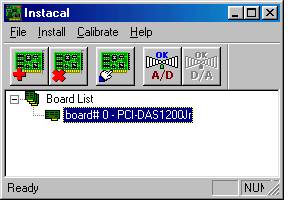
2.
The Plug and Play Board Detection menu will then be opened.
This menu will display any boards that were detected during the
bootup process. Make
certain that the PCI-1200JR board has a checkmark in the indicator box.
Select OK to proceed.
3.
Select Install, Configure (or the Configure icon) to display the board properties.
You should only change the # Channels from 8 Differential to 16
Single-Ended. Select OK to proceed.
4.
Close the InstaCal window.
Congratulations!
You have successfully installed and connected the ComputerBoards A/D
card for use with the Ariel Performance Analysis System (APAS) and are
ready to use the ARIEL ANALOG program.
Return-Path: <Wise80x86@aol.com>
From: Wise80x86@aol.com
Date: Thu, 19 Nov 1998 11:14:53 EST
To: ariel1@ix.netcom.com
Cc: gideon@arielnet.com
Subject: Computer Boards
Stan/John-
I have contacted Computerboards regarding the difficulty we encountered a few
weeks ago when you tried to install a system with a board. If my recollection
is correct, there was a problem when we used the new version of the CB setup.
CANA could not execute because the system could not find something or another.
We solved the problem by going back to an older version of theeir Install.
I cannot remember the details and the people at CB drew blanks when I vaguely
described the problem. So I need you to go thru the process of installing a
board on a system with the new CB Install and give me a detailed description
of the problems that develop. Or, should you remember, just pass this info
along to me. It appears that the bulk of our contact regarding this was over
the phone as I have almost no e-mail regarding it.
Thanks, Jeremy
Stan & I are both correct on the issue of powering
electrodes with the new CES 16 channel board. If the board does NOT have the DC-DC
converter installed on the board, there is no on board power for the electrodes and 9v
batteries must be used. However if the DC-DC converter is mounted on the board then it can
power the electrodes depending on the setting of the jumpers. With CES, the DC-DC is
always mounted.
I have installed the PCI analog board in my system
& I think I understand the nature of the problems which have been encountered trying
to get the PCI version of the boards working.
It basically boils down to this. The board will
not work properly if it is sharing an interrupt# with another board. It is easy to check
this. Go to Device Manager, highlight "Computer" and click on the properties
button. A listing of the interrupt#'s and the boards which use them will appear. Int #9 is
where I find my A/D board. If there are other boards listed as using this same interrupt
the A/D does not work. If you find another board using this interrupt go to the properties
for that board and check the "Disable" checkbox. You do not need to re-boot the
computer. The device should become disabled. Now try the Analog program. It should work if
all of the sharing boards are so disabled.
I contacted Computerboards about this & they
confirmed that the board indeed will not work if there is interrupt sharing. They have a
fix in the form of an updated version of CBW32.DLL. Their WEB site is currently down. I
will get it as soon as I and check it out and send it off to you if the problem is solved.
Jeremy,
Yes, the interrupt problem is a problem we know about and we do go ahead and try to
isolate the board to it's own IRQ.
But we still see a problem that when we first install the board in a new system by
itself(video card only other card installed) the APAS analog will not see the board. This
board on this computer is on IRQ5.
When I put the board into another slot and try it the program works.(board is still on
IRQ5)
I then put the board back in the original slot on IRQ5 and it still works with the analog
program.
Not a big problem for us, but it is consistent for the last few systems we put together.
Stan
At 02:43 PM 05/26/2000 -0400, you wrote:
>>>>
I have installed the PCI analog board in my system & I think I understand the
nature of the problems which have been encountered trying to get the PCI version of the
boards working.<?fontfamily> It basically boils down to this. The board will not work properly if it is
sharing an interrupt# with another board. It is easy to check this. Go to Device Manager,
highlight "Computer" and click on the properties button. A listing of the
interrupt#'s and the boards which use them will appear. Int #9 is where I find my A/D
board. If there are other boards listed as using this same interrupt the A/D does not
work. If you find another board using this interrupt go to the properties for that board
and check the "Disable" checkbox. You do not need to re-boot the computer. The
device should become disabled. Now try the Analog program. It should work if all of the
sharing boards are so disabled. I contacted Computerboards about this & they confirmed
that the board indeed will not work if there is interrupt sharing. They have a fix in the
form of an updated version of CBW32.DLL. Their WEB site is currently down. I will get it
as soon as I and check it out and send it off to you if the problem is solved. Jeremy
<?/fontfamily>
<?fontfamily> <?param Arial>
<?param Arial> <?/fontfamily>
Cornwell Andrew
From: Wise80x86@aol.com
Date: Fri, 18 Dec 1998 10:17:34 EST
To: ariel1@ix.netcom.com
Subject: Re: EMG data collection
John-
Clearly a number of the settings are wrong. This is how they should be set.
Board type = CIO-DAS16/330
Base address = 300
Interrupt level =7 *
DMA level = 1
Clock speed = 10 MHz *
# of channels = 16 single ended
operation mode = enhanced
external memory board = not installed *
counter # = 0 source = external *
expansion board = not installed *
In a message dated 12/17/98 9:50:50 PM Eastern Standard Time,
ariel1@ix.netcom.com writes:
<< Hello John:
>
> Now that Fall quarter is over and the final grades are in, Naz and I are
>finally free to spend the necessary time required to become familiar with
the
>with the APAS equipment. Today, we spent the morning trying to get the EMG
>system to work, but we are still having problems. If you remember, the last
>time we spoke I informed you that the EMG software was not reading the
>analogue signal. Your suggestion was that the analogue board switch settings
>might need re-setting as they could have changed when we re-installed the
>analogue board software (a procedure you recommended that we try in order to
>solve the problem of accessing the Ariel analogue program). To investigate
the
>board settings, you said to access the Instacal program and to just follow
>the instructions in the board manual. If I recall, you also said that you
may
>have had to alter some of the settings from those listed in the manual and
>that you would e-mail me this information if this were the case. However,
>since I have received no further details, I assume that the manual
>information is correct.
> When I opened Instacal, then looked under "install", all the boards
>listed (board # 0 to board # ? (I can't remember how many boards were
>listed)) were labeled "not installed". I therefore clicked on board # 0 and
>selected CIO-DAS16/330 from the list of board type options. I did not change
>anything else, as the rest of the settings appeared to match those of the
>factory default settings. However, there are a few other parameters listed
>that are not in the manual. The full set of parameters displayed are shown
>below, and those not listed on page 1 of the manual (under board set up) are
>labeled with an asterisk:
>
>Board type = CIO-DAS16/330
>Base address = 300
>Interrupt level = 5 *
>DMA level = 1
>Clock speed = 1 MHz *
># of channels = 8 differential
>operation mode = enhanced
>external memory board = not installed *
>counter # = 0 source = external *
>expansion board = not installed *
Normand-
Since the version you are running is dated 4/27/99 & the latest version
available is from 5/20/99 I suspect that you have software from before the
problem was fixed regarding sampling times.
With regards to the scaling problem with the data I am a bit perplexed. I
tested the function which generates channel conversions for the plates and
all seemed to be working properly. The only thing I can think of is that you
are bypassing the step where the software calculates the channel conversions
[volts to user units] from the various property pages of plate
characteristics. When you select Options/Plates/your plate type and you
click on "Ok", a dialog should appear which asks if you want to have the
software calculate the plate conversion factors. You must answer "YES" to
this.
It would be a help if you could collect a small file of data for me to look
at.
Best, Jeremy
-----Original Message-----
From: Normand Teasdale <Normand.Teasdale@pmh.ulaval.ca>
To: Jeremy Wise <jeremy@arielnet.com>
Date: Monday, May 24, 1999 3:33 PM
Subject: Re: ANALOG!
>Dear Jeremy,
>
>I had a look at the data by exporting them and I think I'll be able to
recover a minimum of it without too much problem. As far as the sampling
problem, I have collected a few trials (I did not want to send the file I
collected because it is too big--more than 12 Mb) and was able to more or
less replicate the problem. As you will see when opening the second trial,
the duration was 12 sec at 1500 Hz.
>If you display channels (1-16), I have more than 15 sec of data. Channel
delto gau is actually a 1 Hz signal generator. If you display the Fx, Fy,
and Fz channels, it shows up to 20 sec of data (there were no signals in
this trial, so you only have a baseline). I'm sure of the frequency as I
have calibrated it with a digitial scope (HP). Obviously the base time
appears wrong!
>If you open trial 1 (900 hz, 12 sec) then the duration is less than 12 sec!
>
>The version I used is dated 4/27/99 at 8:33 PM. I know there is a later one
(v 3.5 dated 5/20/99) but I diod not have time to check it out. I'll do it.
>
>Thanks again.
>
>Normand
>At 10:51 24-05-99 -0400, you wrote:
>>Dear Normand-
>>
>>I am quite sure your data is in the files & we will be able to retrieve
it.
>>Please e-mail me your data & I will have a look.
>>
>>The problem you describe with the time period for the data being
incorrectly
>>reported is the same that you reported originally and was fixed [or so I
>>thought]. I will check with Gideon to make sure that the "fixed" version
was
>>posted on the WEB site. What date did you perform the download?
>>
>>As for the other problem of incorrect forces being reported, it would be
>>best if I had a data file.
>>
>>We will get these problems cleared up immedeiately!
>>
>>Thanks, Jeremy
>>
>>-----Original Message-----
>>From: Normand Teasdale <Normand.Teasdale@pmh.ulaval.ca>
>>To: jeremy@arielnet.com <jeremy@arielnet.com>
>>Cc: gideon@arielnet.com <gideon@arielnet.com>
>>Date: Friday, May 21, 1999 1:07 PM
>>Subject: ANALOG!
>>
>>
>>>Dear Jeremy (Gideon/John);
>>>
>>>I have been collected some analog data (AMTI, synch signal and EMG
signals)
>>and a number of odd problems have occurred. Some of these problems
resembled
>>those I reported a few weeks ago. I have noticed that in the new version
3.5
>>there is an upgrade for the analog module. Unfortunately, version 3.3 does
>>not allow to transfer the license, so I could not try it out to find out
if
>>the problem fixed is indeed related to the problems I have encountered. A
>>description of some of the problems follow. In case the problems reported
>>>As for the problems I encoutered, there were many:
>>>1. Even though I have selected one plate (AMTI), all calibration factors
>>are fine, electronics is selected properly (excitation of 10 v , gain of
>>2000), the values reported are completely off. The person I tested weight
>>about 40 kg and I get Fz values of 3 kg! (it is not because I zeroed the
>>platform with the person being on it!!!). Midway through my collection
>>session, I rebooted the PC and it did not change anything. I created
another
>>file as I thought the original might have been corrupted, without more
>>success. I was collecting 11 channels at 1500 hz for 12 s. I tried other
>>sampling frequency as well (300, 600, 900, 1200, . . .) but I still had
the
>>same problem.
>>>2. I am sure of the problems for Fz, but i suspect, the problems was also
>>present for Fx, Fy, and the moments.
>>>3. At one point, I have reduced the sampling period (12 sec to 8 sec) and
>>all channels only reported a little less than 5 sec! Quite curiously, the
>>plate1-Fx, plate1-Fy, and plate1-Fz gave 8 sec of data even though only 5
>>sec were shown for the 6 channels of AMTI collected data!!!
>>>4. When i collected for 12 sec, it showed up 18 sec of collected data . .
.
>>but 12 sec for the plate results! I tried at 150 Hz and got less than 2
sec
>>displayed! 900 hz gave a little more than 10 sec!!! All plate data were
>>always nowhere close to reality.
>>>
>>>I can send a file if you need but I am sure you probably have figured out
>>the problem?! Is there anything I can do to recover these data . . . or
are
>>they lost forever!
>>>
>>>Best regards,
>>>
>>>Normand
>>>
>>>
>>>
>>>Normand Teasdale (Normand.Teasdale@kin.msp.ulaval.ca)
>>>Universit� Laval, Laboratoire de performance motrice
humaine, PEPS
>>>Facult� de m�decine
>>>D�partement de m�decine sociale et pr�ventive
>>>division de Kin�siologie
>>>Qu�bec, Qu�bec G1K 7P4
>>>T�l: (418) 656-2147
>>>Fax: (418) 656-2441
>>>
>>
There are many ways of doing it. One of the simple one is to build a
pulse generator. It cost around $5 in Radio Shack. Then you use a switch to light a
LED or any light that the camera can see and in the same time send a 1 or 2 volts to one
of the A/D channels. This synchronize the camera with a signal on the A/D and if you have
EMG on the other channels you can synch them accordingly.
Another simple method, is to put a large monitor in the background of
the video location where the camera can see the monitor. Then use the Oscilloscope
function for the EMG and you will see the movement and the monitor in the background with
the EMG signal appear on it to synch the two.
----- Original Message -----
Sent: Friday, May 28, 1999 3:35 AM
Subject: EMG synchronistion
> Dear Gideon,
>
> Could you please give me some advice regarding how you
> can synchronise EMG with the APAS, so that I am able
> to determine events during a gait cycle on the EMG
> data.
>
> The EMG system we use allows an external marker to be
> used and I have thought about using footswitches.
> Unfortunately, I don't have access to any footswitches
> at the moment and I was wondering if there was any
> other methods that you have used or know about to
> allow such synchronisation.
>
> I would be grateful for any such information.
>
> Regards
>
> Steve Blackburn
>
> ===
> **Steve Blackburn
**
> **Dept Sport & Exercise Sciences **
> **School of Sciences
**
> **University of Sunderland **
> **Sunderland SR2 3SD
**
> **England
**
> **Tel. (0191) 515 2000 ext.4800 **
> _________________________________________________________
> Do You Yahoo!?
> Get your free @yahoo.com address at http://mail.yahoo.com
>
as usual, thanks so much for your prompt response.
I will try it tomorrow
leonard
Ariel wrote:
> Hi Leonard,
>
> The EMG module is an older "subset" of the Display module. Instead of
> using the EMG module, I suggest that you use the DISPLAY module. Just pull
> up an ANA (analog) file instead of a 3D (video) file. Then you will have
> all the same options as the video. Refer to the Help screens for
> additional information.
>
> I hope this information is helpful!
>
> Sincerely,
>
> John Probe
> Email: ARIEL1@ix.netcom.com
>
> At 09:39 AM 11/01/1999 -0500, you wrote:
> >john,
> >
> >thanks for helping out cecilia orazi . . . much appreciated
> >
> >relative to her project, and others i suppose . . . is there a labeling
> function
> >I can use in the EMG module? hate to have to export just to get some
> max, min,
> >and timing data?
> >
> >suggestions?
> >
> >-leonard
> >
> >
> >Ariel wrote:
> >
> >> Hello Cecilia Orazi,
> >>
> >> Based on the information you have provided, a Site Key has been generated
> >> for your system.
> >>
> >> Site Code: DB14 1AB5 7F3E 22E1 E8
> >> Site Key: F61D D359 5473 12F2 5384 3C4A
08
> >>
> >> We hope this helps with your thesis. Please provide the references to
your
> >> thesis and any other publications/presentation so we can include them in
> >> the Ariel bibliography.
> >>
> >> good Luck!
> >>
> >> John Probe
> >> Email: ARIEL1@ix.netcom.com
> >>
> >> At 05:22 PM 10/29/1999 -0400, you wrote:
> >> >Dear Gideon and John;
> >> >This is Cecilia Orazi, Dr. Len Elbaum's grad student at
FIU. I came
> home to
> >> >continue working with the APAS system, and just realized I don't have
the
> >> >site key yet, so it is not working. Could you please give me one? I will
> >> >need it for 2 semesters, if it's OK with you.
> >> >The site code is DB14 1AB5 7F3E 22E1 E8
> >> >My computer is an IBM Aptiva, Pentium 200mHz, 64 MB RAM.
> >> >I don't know if you need other information, but if you do, just let me
> know
> >> >and I'll send it right away.
> >> >I'll really appreciate if I can get the site key at your earliest
> >> >convenience to be able to work at home, since the lab at FIU is freezing
> >> >cold, and I have a lot of work to do to finish this thesis.
> >> >Thanks in advance. Sincerely,
> >> >Cecilia Orazi
> >> >cecili3@attglobal.net
> >> >
> >> >
> >
> >Attachment Converted: "F:\MAIL\ATTUCH~1\elbauml.vcf"
> >
Hello Slobodan Jaric,
Thank you for your message. There are several items that should be checked
to initiate triggering in the analog module. First, what channel is set as
the trigger channel. This is labeled in the TrigCh immediately below the
toolbar. When using the force plate, I usually set this to the FZ channel
as this is the applied force perpendicular to the top surface of the plate.
Secondly, check the trigger level. This is indicated in the TrigLev field
immediately below the toolbar. If the trigger level is set too high, the
sample will not be triggered. Sampling can be initiated using the keyboard
by setting this value to a large negative number (-999 for example).
Ideally, you just need a value smaller than the anticipated signal to use
the keyboard as the trigger.
Also, make certain that the trigger channel in one of the active channels.
The last active channel is indicated in the LastCh entry under the toolbar.
If for example, the last channel is set to B and the trigger channel is C,
then the sample will not be triggered.
I hope this information is helpful. Please contact us for any additional
information.
Sincerely,
John Probe
Email: ARIEL1@ix.netcom.com
At 02:28 PM 04/10/2000 +0200, you wrote:
>Another question:
>
> We connected the platform, the A/D bord works (checked with
InstaCal), all
>parameters are sat but, somehow, we cannot triger sampling in Analog
Modul!
>By the way, is there any way to start sampling from the keyboard?
>Rgards
>****************************************
>Slobodan Jaric
>Centre for Musculo-Skeletal Research
>National Institute for Working Life
>Box.7654
>S-907 13 Umea
>Sweden
>
>Tel: /46-90-176121
>Fax: /46-90-176116
>****************************************
>
We checked all options (different trig. channels, different trigger values,
different last channals) but the data acquisition was not initiated. I
repeat, according to the InstaCal program, the A/D board works.
Regards
At 12:31 2000-04-10 -0700, you wrote:
>Hello Slobodan Jaric,
>
>Thank you for your message. There are several items that should be checked
>to initiate triggering in the analog module. First, what channel is set as
>the trigger channel. This is labeled in the TrigCh immediately below the
>toolbar. When using the force plate, I usually set this to the FZ channel
>as this is the applied force perpendicular to the top surface of the plate.
>
>Secondly, check the trigger level. This is indicated in the TrigLev field
>immediately below the toolbar. If the trigger level is set too high, the
>sample will not be triggered. Sampling can be initiated using the keyboard
>by setting this value to a large negative number (-999 for example).
>Ideally, you just need a value smaller than the anticipated signal to use
>the keyboard as the trigger.
>
>Also, make certain that the trigger channel in one of the active channels.
>The last active channel is indicated in the LastCh entry under the toolbar.
> If for example, the last channel is set to B and the trigger channel is C,
>then the sample will not be triggered.
>
>I hope this information is helpful. Please contact us for any additional
>information.
>
>Sincerely,
>
>John Probe
>Email: ARIEL1@ix.netcom.com
>
>
>
>At 02:28 PM 04/10/2000 +0200, you wrote:
>>Another question:
>>
>> We connected the platform, the A/D bord works (checked with
InstaCal), all
>>parameters are sat but, somehow, we cannot triger sampling in Analog
Modul!
>>By the way, is there any way to start sampling from the keyboard?
>>Rgards
>>****************************************
>>Slobodan Jaric
>>Centre for Musculo-Skeletal Research
>>National Institute for Working Life
>>Box.7654
>>S-907 13 Umea
>>Sweden
>>
>>Tel: /46-90-176121
>>Fax: /46-90-176116
>>****************************************
>>
>
>
****************************************
Slobodan Jaric
Centre for Musculo-Skeletal Research
National Institute for Working Life
Box.7654
S-907 13 Umea
Sweden
Tel: /46-90-176121
Fax: /46-90-176116
****************************************
Hello Petros Tsintzos and Dr. Christos Papadopoulos,
The Analog hardware/software included in your original APAS computer is based on the DOS
operating system. Technology has changed drastically in the last 4 years. The current
hardware/software operate from the Windows environment. Unfortunately, the DOS based
hardware will not operate in the Windows environment. The Windows system requires new
hardware and software.
The same is true for the video hardware. The "new" APAS computers include
Digital Video frame grabbers that are not compatible with the "older" analog
video frame grabbers. The JVC 9800 is a digital camcorder that takes advantage of the new
frame grabber.
If you wish to purchase the current APAS with two JVC 9800, you could use the
"new" computer for the video data collection and keep the "old" APAS
for collecting analog data. If you wish to collect data on the "new" computer,
then you must purchase the analog hardware & software.
I hope this information is helpful.
Sincerely,
John Probe
Email: ARIEL1@ix.netcom.com
At 03:40 PM 04/11/2000 +0300, you wrote:
>>>>
Dear Mr. Probe Last November I had received your e-mail that propose 3 option for
updating our APAS system (its 4 years old in windows 3.1). Now we strongly intereste to
buy the APAS software with two JVC 9800 camcorders. We have also the 16 - channel Analog
Hardware-software(connect the Kistler force plate and EMGs). How it is possible to work
together the new APAS software (that included in the package of $10,000
USD) with the our
old analog hardware? Please send me more
informations. Thank you in advanced. Best regards
Petros Tsintzos <?bigger>isplus@spark.net.gr or
<?bigger>Christos Papadopoulos, Ph.D.
***********************************
RISTOTELES UNIVERSITY of THESSALONIKI
Department of Physical Education and Sport Sciences, Serres
Biomechanics Laboratory,
Christos Papadopoulos, assist. Professor
Agios Ioannis, 62 110 Serres
tel. & Fax ++31-991046, mob. 0932-755011
e-mail: chrispap@phed-sr.auth.gr
Hello Ivan Mitzev,
Thank you for your interest in the Ariel technology. I will
provide
answers below each of your questions.
Please review the information and feel free to contact us for any
additional information.
Sincerely,
John Probe
Ariel Dynamics, Inc.
Email: ARIEL1@ix.netcom.com
At 09:09 AM 07/06/2000 DST, you wrote:
>Dear ARIEL,
>
>I'm interested from your system for force plate and EMG. Could you
send me
>more information about it.
>
The Ariel product information can be found on the Ariel internet site.
I
have listed the direct address to specific areas of interest.
Ariel Internet Main Page
www.arielnet.com (or www.arielweb.com)
APAS Product Information
www.arielnet.com/Main/adw-04.html
Comparison of Commercially Available Systems
www.arielnet.com/topics/comparison/default.htm
Selected Applications Of APAS
www.arielnet.com/Main/adw-85.html
Selected Publications Utilizing the Ariel Technology
www.arielnet.com/Main/adw-86.html
APAS Price List
www.arielnet.com/Main/adw-54.html
>I have some questions:
>1. Is it a separate module- can I buy it without video system?
>
Answer 1
========
We do not sell the Analog Module as a "stand-alone" module.
The Basic APAS
is required for complete analog operation. In order to sample
analog data,
one would require the following APAS items.
Basic APAS (Hardware & Software) $10,000
Analog Hardware $7,500
Analog Software $1,500
============================
Total $19,000.00 USD
However, Dr. Ariel has agreed to reduce the price of the Basic APAS to
$7,500 (instead of $10,000) for your circumstances. This means
the total
would be $16,500.00 USD plus shipping charges.
>2. How many channels use this system like analog inputs?
>
Answer 2
========
The standard Analog Module is 16 analog channels.
>3. Which is frequency band of these channels?
>
Answer 3
========
The specs on the Analog module are:
16 Channel Analog Input
Individual BNC and RJ-11 Input Connectors For Each Channel
Input Voltage Ranges: �10V, �5V, �2.5V, �1.25V, 0 to 10V, 5V,
2.5V, 1.25V
Range selection: Software programmable
330 Khz Sample Rate
12 Bit / Channel Data Resolution
>4. What exactly does this software- acquisition, saving of
signals,
viewing or
>treatment of signals. What kind of treatments do you have on it?
>I'll be very glad if answer me and if we keep contacts in a
future.
>
Answer 4
=========
The Ariel software provides extensive analysis capabilities including
Ariel Analog Module supports collection of analog data input.
AMTI,
Bertec and Kistler force platforms are supported with an additional
Real-Time COP and VECTORS programs. Force platform software also
supports
two plates simultaneously. EMG analysis software includes
Normalization,
Rectification, Power Spectrum, Envelope, Spike, Integral, and Median
and
Average frequency. Data can be output to the printer, ASCII or
Lotus/Excel
Worksheet files.
Additionally, you can download and/or view the Ariel Analog Software
manual
from the Ariel internet site. The direct address for viewing is:
www.arielnet.com/APAShelp/CAna/intro.htm
>Sincerely
>Ivan Mitzev
>
>
>
>
>____________________________________________________________________
>Get free email and a permanent address at http://www.netaddress.com/?N=1
>