|
|
Hardware |
[FrontPage Include Component] |
|
|
|
|
|
|||||
|
NAVIGATOR: Back - Home > Adi > Services > Support > Tutorials > Gait > Chapter3 : |
|||||
|
|
|||||
| |||||||||||||||||||
|
Hardware
Categories
|
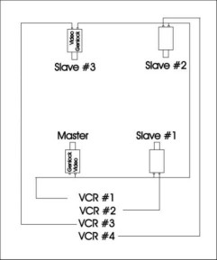
3.2 Required hardwareA typical gait lab will normally contain video cameras and video tape recorders (VCRs) or camcorders, computers with analogue to digital converters, force platforms, video lights, markers, synchronization devices and photo-cells. In the following paragraphs all this hardware will be described briefly. 1. Video camerasA big advantage of a video camera is that it need not be operated to the same extent as a camcorder, which has a built-in tape recorder. Accordingly, cameras may be fixed on the walls of the laboratory and only operated occasionally. Another advantage of cameras is that they may be electronically inter-connected by "genlock" to expose single pictures (video fields) simultaneously (see below). For a two-dimensional analysis with only one camera it may be convenient to grab the video-sequences directly to the computer using the Capture or RealCap program, however, using several cameras for a three-dimensional analysis requires the use of a video tape recorder (VCR) for each camera. Several VCRs may be placed together, which will make the recording of several cameras easy to operate. It is recommended that the VCRs should be at least of a semi-professional quality to ensure a sufficient quality of the video-signals. Otherwise, later automatic digitization of markers may be impaired. 2. GenlockNormal video cameras expose 60 (NTSC) or 50 (PAL) frames per second. This frame rate has proven sufficient for walking, however, using several cameras implies that the exposure of the cameras may be up to 8.3 ms or 10 ms (one half of a frame) out of phase with each other. This may be considered a minor error, but it can easily be excluded by the "genlock" facility built into most camera types of a "semi-professional" quality. The cameras will normally have two BNC connectors, one for video output and one for genlock input. The genlock signal itself is not a simple pulse, while it is actually the full video signal. One camera must therefore be selected as the "master", and the video signal from this camera should be looped to the genlock input on the remaining cameras, which are termed "slaves" (figure 3.2.1). Each camera must be set up as master or slave.
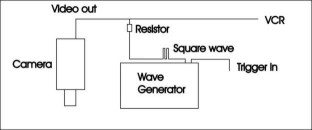
FIGURE 3.2.1 It may happen that the video signal of the master camera becomes too week, because it will be split in two: 1) to the VCR and 2) to provide genlock for the slaves. In such a case a commercial video-amplifier may be used to amplify the signals. If an electronic signal is used (see below) to mark the first frame for analysis on all cameras, the position of this signal on the frame may be used to verify that genlock works. 3. ShutterA camera operating at 60 frames per second takes 16.7 ms (0.00167 seconds) to expose one frame. An example from a normal subject walking at 4.5 km/h (1.25 m/s) shows that the horizontal velocity of the ankle marker reaches 3.9 m/s during the swing phase. This means that this ankle marker will travel 6.5 cm during the exposure of one frame and that it will appear lengthy and "blurred" on the video. A camera of a sufficient quality will have a "shutter" facility to deal with this phenomenon. The shutter defines the duration of the exposure of each frame. Shutter values will normally be: 1/125, 1/250, 1/500 1/1000 up to maybe 1/10000 of a second. Setting the shutter to 1/500 will reduce the movement of the ankle marker mentioned above to 0.78 cm, which will normally be quite sufficient. However, the faster the shutter the more light is required for the cameras. 4. Analogue to digital conversionThe Analogue program in the APAS system is designed to collect analogue signals from e.g. force platforms and EMG amplifiers. Force platforms from AMTI and Kistler are known to the software, which means that the calibration constants of the specific platforms are already present in the software and allows for calculation of the center of pressure under the foot during the stance phase of walking. The physical size of the platforms are also known and the distance between two platforms can be entered by the user. The gain of the platform amplifiers can also be changed by the user like the gain of EMG amplifiers. A marker used for the video analysis has to be placed on the first platform (see description of inverse dynamics). The Analogue program will normally be set to sample the signals at 1000 Hz per channel. A data sampling is always initiated by a "trigger". The simplest form of trigger is a keyboard trigger, which means that the user must hit the keyboard to start the sampling process. An analogue trigger is more sophisticated since it may be used to synchronize between analogue sampling and the video recordings (see next paragraph). A special facility is called "pre-trigger function". This implies that the analogue sampling will contain data from before the trigger was initiated. The pre-trigger time interval can be defined by the user. If e.g. the pre-trigger signal is defined to be the vertical force on the first platform, sweep duration set to 2000 points/channel, the trigger level set to 10 Newton and the pre-trigger interval to 10% out of 2000 ms, then the sweep sampled will contain data points 200 ms prior to heel strike on the first force plate. 5. Event synchronizationIf recordings from analogue devices like force platforms and/or EMG amplifiers are required to be synchronized to the video recordings some sort of synchronisation device will have to be used. If would be tempting to use heel strike as an event and use the pre-trigger function of the Analogue program. However, the exact frame of heel strike is very difficult to spot on the video and there could be an error of at least one video frame. A more accurate solution would be to built a simple electronic device, which would turn on one or more light emitting diodes (LEDs) when the vertical force of the first platform exceeds e.g. 10 N. Then one would know that the first video frame with light on the LEDs corresponds to heel strike, and it would further be possible to count 10 frames backwards in the Trimmer program to include the 200 ms prior to heel strike. This example assumes that the video runs at 50 Hz, which means 20 ms per frame. The LEDs should be placed somewhere in the field of view, so that each camera can see an LED. Actually it is possible to place one LED within a few mm from the lens in one of the corners of the field of view. Although such an LED would be totally out of focus, it would still put a rather large "splash" on the video recording. Another solution is to place a photo-cell in front of the first force platform. The photo-cell should then be connected to device, which would light the LEDs and send an analogue trigger signal to the Analogue program. In this case an additional channel has to be defined for the trigger signal. Finally, the LEDs and the trigger signal could be initiated "by hand", i.e. by pushing a button just before heel strike. When using more than one camera an event will also have to point out exactly the same frame on each camera. The simplest way is in fact to drop a bouncing ball in the field of view just before the subject enters the recording volume. If the ball moves fast enough, it will be possible to identify the same frame on each camera. However, this simple approach will only do when no synchronisation is required to analogue signals and it is often inconvenient to have a ball bouncing in front of a walking subject. The LEDs mentioned above would be far better, but it is also possible to put an electronic marker on each video camera. This can be accomplished very simple by use of a commercial wave-generator connected between the camera and the VCR (figure 4.2.2). Accordingly, it will not work with camcorders.
FIGURE 3.2.2 If the wave-generator is set to output 5-6 square-wave pulses at 1kHz it will be seen as a clear disturbance on one video frame. Furthermore, if the cameras are genlocked, the disturbance will display the same position on all cameras. The wave-generator may be triggered by hand or by a trigger signal coming from a force platform or a photo-cell. 6. Photo-cellsTo control the walking speed of the subjects it is often convenient to place photo-cells before and after the force platforms. Optimal placement of the photo-cells would be at the height of the head. However, it is also possible to record the leading trailing leg at a height of about 15 cm above the floor. Calculations of the "real" walking speed by differentiation of a hip marker can be used to test the reliability of photo-cells. The first photo-cell may also be used to trigger synchronization of cameras and analogue data sampling. 7. Video lightsFor a two-dimensional recording with one camera, it is recommended to direct a strong light source perpendicular to the subject and the direction of movement. For a three-dimensional recording with several cameras it may be possible to use rather small video-lights mounted on top of the cameras. The cameras should then be positioned relatively high pointing downwards to avoid cameras being disturbed by lights of opposing cameras. Light may also be directed towards the ceiling to distribute it more even. 8. Calibration cubeFor a two-dimensional analysis the APAS system requires four or more none co-linear points with known spatial coordinates. It is essential to place the calibration points exactly in the plane of motion, not nearer to the camera not farther away - otherwise the scaling will be incorrect. It is also important for a two-dimensional analysis that the camera is positioned perpendicular to the plane of motion and the camera has to be leveled to the horizontal plane.
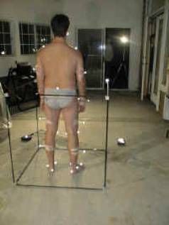
For a three-dimensional analysis it is necessary to use a calibration cube. Such a cube is normally provided with the APAS system. It consists of 8 or more calibration points positioned in a three-dimensional space at known coordinates. It is required that the cube is leveled with respect to the horizontal plane and it is convenient if the x-direction of the cube is positioned along the plane of walking progression. The cameras are not required to be leveled. |
|
|