![]()
![]()
![]()
![]()
![]()
|
|
|
|
Transformation - DLTThe computation phase of
analysis is performed after all camera views have been digitized.
The purpose of this phase is to compute the three-dimensional image space
coordinates of the subject�s body joints from the relative two-dimensional
digitized coordinates of each camera�s view.
The ARIEL TRANSFORMATION software is a Windows based program for
performing this conversion process. Transformation is the
process of converting two or more, two-dimensional digitized views into a
three-dimensional image sequence. The
transformation option is also available to convert a single, two-dimensional
digitized view into a two-dimensional image sequence. In either case, the process involves transforming the
relative digitized coordinates of each point in each frame to absolute image
space coordinates. This process is
performed entirely by the computer. Some
initial timing information will be requested, after which the transformation
will occur automatically. Although a few of the TRANSFORMATION�s
features may appear complex, they are relatively easy to master once you
understand the underlying concepts. This
manual is arranged to teach you these concepts in a logical order by showing
you, in step-by-step fashion, how to use TRANSFORMATION. A few of the new features
you will see in TRANSFORMATION version 1.0 1.
Stick Figure Display. Stick
Figures are displayed for each camera view as well as one for each of X, Y, and
Z axes. 2.
Transformation Parameters. Display
DLT and PPT transformation parameters for each view. 3.
Support For Panning Cameras.
Views utilizing either the Ariel Panning head or any panning camera can
be transformed for analysis. 4.
Synchronizing Algorithm.
A newly developed Synchronizing Algorithm determines relative error in
synch time between views. 5.
Automatic Smoothing.
Smoothing can be accomplished automatically using user-defined smoothing
values. 6.
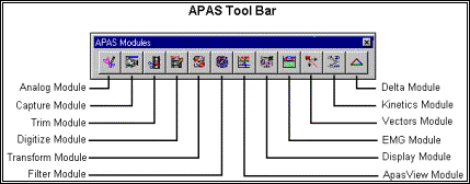
APAS Tool Bar. A toolbar has been added
to allow the user to activate individual APAS modules from within the main
programs. The following table
provides the basic guidelines for minimum and recommended hardware to provide
the best possible performance. The
software requires a minimum of Microsoft Windows 95/98 and APAS-2000 Revision
1.0 or later. Component
Minimum
Recommended _____________________________________________________________________________________________________________________________________________________ Pentium
Computer
Pentium 233
Pentium II 333 MHz or higher Video
Display
S-VGA (256 Colors)
High Color Display (65,000 colors or more) RAM
32 MB
64 MB or more 1.
Double-click the TRANSFORM icon located in the APAS System
window group. The main TRANSFORMATION window will appear. Prior to performing the
transformation process, you should take the time to familiarize yourself with
the format and contents of the various screens listed below: THE APAS TOOL BARYou can activate any of
the APAS software modules from within the current program by selecting the icons
located on the APAS tool bar. The
tool bar is toggled on/off using the APAS Toolbar command in the VIEW menu.
A check mark in the left column of the menu indicates that the toolbar is
currently active. The toolbar can
be re-located anywhere in the main program window by dragging it with the mouse.
Clicking the appropriate icon can activate the following program modules.
Icons are pictorial representations of programs, commands or functions.
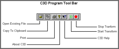
THE TOOL BARYou can activate many
functions by selecting the icons located on the TRANSFORMATION program
tool bar. The tool bar is located
near the top of the window. Icons
are pictorial representations of commands or functions. You can access the following commands by clicking the
appropriate icon.
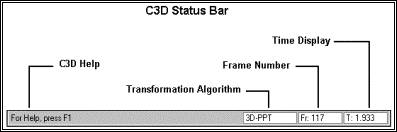
THE STATUS BARThe status bar provides
useful information about the current image status of the file during the
Transform process. The status bar
is located at the bottom of the TRANSFORMATION window.
The far-left side of the status bar is divided into three separate
fields. The left field displays the transformation algorithm being used.
Available options are 2D-Multiplier, 2D-DLT, 3D-DLT and 3D-PPT.
The middle field displays the current Frame number as the sequence is
being transformed. The right field
displays the current Time value as the sequence is being transformed.
1.
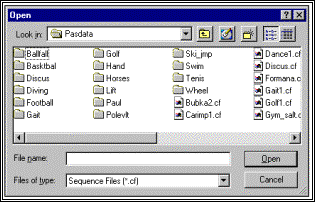
Choose the OPEN command from the FILE menu.
The OPEN File Dialog box will appear.
The
OPEN File Dialog box looks for a particular type of file (files that have the
extension of (*.CF). This
file is automatically created when a New Sequence is established in the APAS
DIGI4 module. The OPEN File Dialog
box can be used to specify the Drive, Directory, and Name of the sequence file
to be retrieved. Select the
sequence name to be transformed and then select OPEN to proceed.
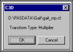
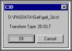
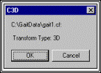
A
small window will appear indicating the path of the *.cf file and the algorithm
that will be used for the transformation. The
Transform Type is automatically determined by the software and is based on the
control point coordinates entered in the Digitizing module. The
Multiplier algorithm indicates that only 2 control points have been
specified. Only two-dimensional
analysis can be performed using this algorithm. NOTE: The Z
coordinate must be zero for 2D transformations.
The
2D-DLT algorithm indicates that 4 or more coplanar control points have
been specified.
The
3D algorithm indicates that 6 or more non-coplanar control points have
been specified. Three-dimensional
transformations require a minimum of two views.
Select
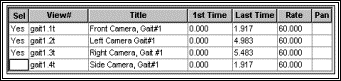
OK to proceed. All the
existing views for the associated *.CF file will be displayed one per row in a
grid. 2.
Select the views to be Transformed by double-clicking anywhere on the
grid row of the desired view to toggle the �SEL� state for the row.
A �YES� entry in the SEL column indicates that particular view will
be included in the Transform process. If
the SEL column is blank, the view will not be used in the Transform process.
NOTE: At least 2 views
must be selected for 3-Dimensional data.
3.
Select the TRANSFORM command from the 3D menu (or select
the 3D icon in the tool bar) to start the Transformation process.
A menu box will be displayed where the user may select 1st/Last times and
a data rate. Select OK to proceed
with the transformation process using the values specified in the Transformation
Parameter menu.
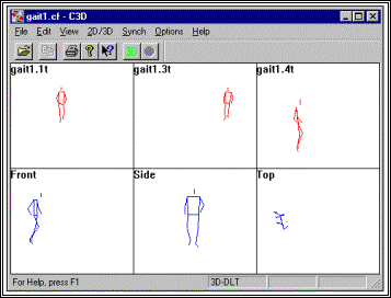
Stick figures will appear on the monitor, one for each view and one for
each of the X, Y, and Z-axes as the transformation takes place.
A confirmation screen will appear when the 3D Processing is complete.
5.
The STOP command can be selected from the 3D menu to abort
the transformation process. STOP
can also be activated from the Tool Bar icon. 6.
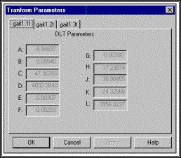
Upon completion of the Transformation, select the DLTs_etc command
from the 3D menu to see the actual transformation parameters.
TIME MATCHING INFORMATIONIf a three-dimensional
transformation is being performed, an additional operation must be performed on
the individual camera views to synchronize them. This process is called time matching. Since each digitized camera view may start at a different
point in time, frame one of the first view may not correspond to frame one of
the second view. The transformation
will only yield accurate results if digitized coordinates from simultaneous
frames are used. The TRANSFORMATION
software utilizes the synchronizing event from each of the views as a basis for
time matching. The time for each
frame in each view is adjusted relative to the synchronizing event so that all
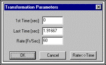
the synchronizing events occur at the same absolute time. 1st Time (sec)
The 1st Time is the starting
point in time for the resulting image sequence. Since the image sequence is created by combining information
from each of the views, the sequence should not start until the view with the
highest 1st-Time value starts. It
is possible to specify that the image sequence should begin at a later time if
the information from the beginning of the digitized views is to be omitted.
In most cases, the image sequence is captured and digitized from a
synchronized point, so this field will be zero. Last Time (sec)
The Last Time is the ending
point in time for the resulting image sequence. This value is computed by multiplying the number of images
captured minus 1 by the frame rate entered in the DIGI4 module.
For example: A sequence of 30 images captured at a Frame Rate of 60
images per second would have a Last Time of 0.483333 seconds. Last Time = (30-1) * (1/60) = 29/60 =
0.483333 seconds It is recommended that the default
value be used unless a specific data interval is required for analysis. Rate (Fr/Sec)
The Rate is the time between
data points for the resulting image sequence.
Image sequences do not have to have the same frame rate as the individual
views. The TRANSFORMATION
module will automatically interpolate linearly between digitized frames to
create any resulting frame rate desired. For
example, suppose views were recorded at the standard video rate of 60 Hz (1/60 =
.0166 sec), but it is desired that the resulting image sequence has an apparent
frame time of 0.01 seconds (100 images/second), then a value of 0.01 would be
entered for Rate. NOTES:
First,
setting Rate to a very small value will create a large number of frames that
will slow the analysis process and can possibly exceed the capacity of some of
the analysis modules. It is NOT recommended to create sequences with more than 1000
frames. Second,
the analysis system cannot manufacture data.
A higher frame rate will produce more stick figures; however, there will
be no more actual information available than in the original digitized data.
A tennis swing recorded at 60 images/second cannot be used to analyze the
impact interval at 500 images/second. The
information is just not there! For
this reason, it is recommended that a time interval close to the digitized data
interval be selected. One major contribution to
error in 3D studies is the inability to accurately determine the synchronization
between cameras that are not gen-locked. This
is often achieved by trying to locate a synchronizing event or impact, a process
that is accurate to .5 frames at best and may actually be several frames.
The "SYNCH" command added to ARIEL TRANSFORMATION
is a software feature that employs a newly developed algorithm to determine the
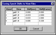
relative error in the synch time. SYNCHRONIZING VIEWSThe steps to synchronize
multiple camera views utilizing the ARIEL TRANSFORMATION algorithm are
listed below. For the Synch
algorithm to work correctly there must be a single data point with a large
amount of vertical (Y) motion. For
example, include as an extra point, a ball falling that is simultaneously
visible from all camera views. 1. Open the desired Sequence File and select the individual
views to be used for the Transformation process. 2. Select the AUTO-SYNCH command from the SYNCH
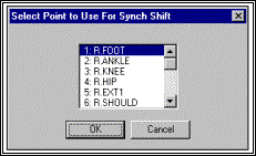
menu. 3. Select the point to be used for the Synch Shift.
As stated above, this should be a single point with a large amount of
vertical displacement. Select OK to proceed.
4. A table of time shifts for the different views is displayed
to the user. The user can accept
the values by selecting OK. This
will update the view files with the new synch times. Cancel is selected to reject the computed values.
SYNCHRONIZING ALGORITHMThe ARIEL
TRANSFORMATION synchronizing algorithm uses the fact that when calculating
3D from two 2D views the situation is over-constrained. Four numbers are used to
calculate three unknown numbers using a least squares criteria.
In such a situation the fit is not likely to be exact and there is a
residual left over from the fitting calculation. The better the fit the smaller
the residual. Think of fitting 3 points to a line. The "best"
fit" may not go through any of the three points.
The deviation from the �best-fit� line is the residual. In the case of 3D
reconstruction, each camera determines a line in 3D space on which the point
lies. In a perfect world the two
lines, one for each camera, would intersect, the point of intersection being the
3D point of interest. In the real
world, the lines don't actually intersect but there is a point of closest
approach with the distance of closest approach being related to the residual. Consider the �ideal�
situation of a normal lab setup consisting of two cameras recording a falling
object. As the object falls, the
two lines of projections track the falling object intersecting exactly at the
falling object. Now think of introducing a synch error so that one camera is now
"seeing" the falling object at an earlier time from the other. For
this camera the line of projection will point too high and the two lines will
not intersect. The earlier the camera �sees� the falling object relative to
the second camera, the greater the "miss" and the larger residual. For this algorithm to
work properly there must be a single point with a large amount of motion out of
the plane that contains the camera projection centers. In most cases, this relates to VERTICAL (Y) motion.
NOTE: If everything is in
one plane this approach will not work! The Ariel
TRANSFORMATION Synch algorithm utilizes a point with large vertical motion
and calculates a total residual value for this point summing over all frames as
follows:
ResidualSQ = SUM( Res[i]**2) for all frames "i"of interest Then the program finds
the time shift that minimizes the above "ResidualSQ". The time shift
that produces a minimum value is the synch error. Several studies have been
performed that suggests the data improves when this analysis is performed.
However other factors could contribute which have nothing to do with a synch
error. For example, suppose one view always has the falling object digitized low
due to the person's digitizing inability to estimate the point center. This
would appear as a synch shift because the program could improve the ResidualSQ
by making that view slightly earlier thus raising slightly the projection line
causing it to more closely intersect the other camera's projection line. Then
for all other points in the study the data would be moved to this slightly
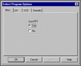
earlier time as well. Selecting the OPTIONS
command from the OPTIONS menu accesses the ARIEL TRANSFORMATION program
options. Available options allow
for the selection of the transformation algorithm and user-selectable colors for
the �stick figure� displays.
TRANSFORMATION ALGORITHMS The ARIEL TRANSFORMATION
program converts digitized coordinate locations to image space coordinate
locations through a process known as �transformation.�
The TRANSFORMATION program provides two possible algorithms for
performing the transformation process: Direct Linear Transformation (DLT)
and Physical Parameter Transformation (PPT).
The desired algorithm can be set by selecting the Options command
from the Options menu. The
PPT algorithm will automatically be used for Panning Camera views. DIRECT LINEAR TRANSFORMATION (DLT)
The traditional method
used to convert digitized coordinate locations to image space coordinate
locations utilizes a widely used method known as the Direct Linear
Transformation or DLT. In this
�mapping� process, the known image coordinates, as well as the digitized
coordinates of the control points, are used to solve a set of simultaneous
linear equations that relate one set of coordinates to the other.
This set of equations is solved using a linear least squares method that
yields the image space coordinates of each point, given the digitized view
coordinates of that point. Colinearity
photogrammetric relations provide the mapping from spatial coordinates to image
coordinates. This mapping is a
function of 16 physical parameters that describe the central projection model of
a camera. The DLT is
obtained from the colinearity relations. The
colinearity conditions may be rearranged into a form requiring 11 coefficients.
These 11 coefficients are functions of the 16 physical parameters.
Minimization of residual error with respect to these 11 coefficients is
linear; thus, the calibration procedure is simplified.
The 11 parameters are the coefficients of the widely used DLT
method. The advantage of this
transformation method over more traditional methods is that one does not need to
know the location or orientation of the cameras, the distance of cameras to the
subject, or any information about the camera or projections lenses such as focal
length and magnification. Instead,
by directly determining the relationship between the image space and each of the
digitized views, all the intervening image changes are eliminated, and need not
be considered. In order to utilize this
method, there must be a known set of control points in the video recording of
each view. At least six
non-coplanar control points are required (though more can be used) for a
three-dimensional analysis. This is
the minimum number of points required to solve the set of simultaneous linear
equations that produce the transformation.
For a two-dimensional analysis using a single camera, at least four
co-planar but non-colinear control points must be used.
It is possible to use more than the minimum number of control points, as
this will increase the accuracy of the transformation.
The control points should be distributed to fill as much of the image
space as practical. If the control
points all occur in a small portion of the image space, then image distortion is
likely to increase as the distance from the image to the control points
increases. PHYSICAL PARAMETER TRANSFORMATION (PPT)
The Physical Parameter
Transformation (PPT), like the Direct Linear Transformation (DLT), is built
upon the colinearity photogrammetric relations. The rotational orientation matrix of the camera with respect
to the spatial coordinate system provides 9 of the 16 physical �mapping�
parameters. If the rotational
orientation matrix of the camera is expressed as a function of three suitable
angles, the number of physical parameters reduces to 10.
Minimization of mapping error with respect to these 10 physical
parameters automatically insures that the resulting orientation matrix is
orthogonal. The minimization is
still nonlinear; thus numerical optimization technique is required along with an
initial estimate for the 10 physical parameters.
The 10 physical parameters may be expressed as functions of the 11 DLT
coefficients; thus, the DLT provides a good initial estimate for the 10
parameters. This photogrammetric
procedure involving 10 physical parameters is called the Physical Parameter
Transformation (PPT). Like the
DLT, once the mapping parameters are known for two or more cameras, spatial
locations of points whose digitizer coordinates are known may be obtained by
solution of a linear system. The PPT may easily
accommodate panning cameras if the displacement of the camera relative to its
calibration position is known. In
addition to the camera�s orientation matrix, the location of the projection
center provides three physical parameters that may vary with the panning angle.
Both camera orientation and projection center are transformed via the
displacement yielding the PPT coefficients for a panned camera position.
View files designated as �Panning Views� will automatically use the
PPT algorithm for the Transformation process.
This algorithm is optional for stationary cameras. PANNING CAMERA VIEWSCamera Views designated
as �Panning Views� will automatically use the Physical Parameter
Transformation (PPT) algorithm for the 3-D transformation.
The Direct Linear Transformation (DLT) is not an option with Panning
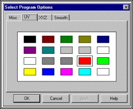
views. UV/XYZ COLORSDuring the transformation
process, stick figure images will be displayed; one for each camera view (UV)
and one for the X, Y, and Z-axis view (XYZ).
Selecting the UV and XYZ tabs allows the user to select the color of the
stick figure display for the UV and XYZ views.
The box around the color indicates the current color setting.
NOTE: Be aware that the
stick figure image will not be visible when the stick figure color is set the
same as the background color.
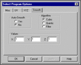
SMOOTHDuring the transformation
process, it is possible to specify that when performing the Transformation that
smoothing be done automatically using some user selected default values.
If further smoothing is required, it is recommended to use the FILTER
program.
Auto-Smooth The Auto-Smooth option is
used to turn the Automatic Smoothing option either ON or OFF.
When this option is set to YES, smoothing will automatically occur during
the Transformation process. If this
option is set to NO, automatic data smoothing is not performed and the settings
for Algorithm and Values are irrelevant. Algorithm The Algorithm option is
used to specify the default algorithm for automatic smoothing.
The available options are Cubic Spline, Quintic Spline, and Digital
Filter. Please refer to the FILTER
program for additional information. Values The Values option is used
to specify the default smoothing values for the X, Y and Z data curves.
For the spline algorithms, these values represent the allowable variance
between the "raw" data and the smoothed data.
Larger values will approximate a straight line while smaller values will
approximate the "raw" data curve.
For the Digital Filter algorithm, these values represent the cut-off
frequency. Please refer to the
FILTER program for additional information. The Ariel Performance
Analysis System (APAS) computes true three-dimensional image space coordinates
of objects from two or more sets of two-dimensional digitized coordinates by a
method knows as Direct Linear Transformation.
The mathematical basis for this transformation is described in this
section. In addition, the APAS can
alternately compute two-dimensional image space coordinates from a single set of
two-dimensional digitized coordinates using the same method.
Since the two-dimensional transformation is actually a subset of the
three-dimensional problem, a separate derivation will not be provided. The APAS considers the
image space (the space in which the activity being studied occurs) to be
described by a right-handed Cartesian coordinate system with a fixed origin and
orthogonal X, Y and Z coordinate axes. An
arbitrary point in the image space is described by its coordinates (x, y, z).
When a film or video recording of an object in the image space is
projected or displayed on a flat screen, the original three-dimensional image is
reduced to a two-dimensional projection. If
a device such as a video digitizer is employed to measure the location of points
on this plane of projection, an arbitrary point can be described by its
horizontal and vertical digitizer coordinates (U,V).
The general form of the transformation between these coordinate systems
may be expressed as: U
=
Ax + By + Cz + D
(1) The coefficients, A
through L, represent various physical parameters defined in the configuration of
the camera and the playback or projection system. In general, it is a difficult process to determine the values
for these coefficients by measurement of camera orientation, distance of camera
to subject, magnification of camera and projection lenses, etc.
If, however, the image space contains an adequate number of points
(control points) whose coordinate locations are accurately known, the
coefficients can be determined through the solution of a set of simultaneous
linear equations relating the image space coordinates of the control points to
the digitized coordinate of the control points. [A]
x1 y1 s1 1 - U1x1 - U1y1 - U1z1 0 0 0 0 U1
(2) Equations (1) and (2) can
be rewritten in matrix form as shown in equations (3) to express the sets of
simultaneous equations that must be solved to determine the coefficients A
through L. Subscripts are used to
denote the image space and digitizer coordinates of individual control points.
A minimum of six non-coplanar control points are required to solve
equations (3), although additional points may be used as indicated by the
ellipses. If more than six points
are used, the set of equations becomes over-determined and may be solved using a
standard linear least squares technique. For a given unknown image
space point (x, y, z), equations (1) and (2) can be rearranged as: {A
- EU}{B - FU}{C - GU}x = {U - D}
(4) The digitizer coordinates
(U,V) are known as the coefficients A through L from the solution of equation
(3). However, equation (4) cannot
be solved for (x, y, z) since this set of linear equations is underdetermined.
Digitized information from one camera is therefore not sufficient to
determine three-dimensional image space coordinates.
This problem can be resolved by the addition of a second camera. For film or video
recordings, each joint location (x, y, z) is a function of time, and therefore,
digitized camera information must be combined for the same moment in time.
This is the purpose of the �Time-Matching� step in the transformation
process. The requirement for
simultaneous digitized information underscores the importance of accuracy in
knowing the camera speed and measuring the synchronizing event for each camera
view. 1. Select FILE, OPEN (or the OPEN icon
in the Toolbar) to Open desired Sequence. 2. Select desired sequence from displayed files. 3. Double-click on the individual views to SET them
for Transformation. *4. Select VIEW, STATUS BAR to toggle the Status
Bar On/Off. *5. Select OPTIONS, OPTIONS and MISC tab to
select the desired Transformation algorithm (DLT or PPT). *6. Select OPTIONS, MISC and the UV and/or XYZ
tabs to select colors for stick-figure display during the transformation
process. 7. Select OPTIONS, MISC and the SMOOTH
tab to activate/de-activate the automatic smoothing option. 8. Select SYNCH, AUTOSYNCH for the optional TRANSFORMATION
Synchronizing program. (Skip to step #9 to bypass this step). 9. Select the desired point with large vertical (Y) movement. 10. Select OK to update Synch times or Cancel to
proceed without any changes to the Synch information. 11. Select 3D and TRANSFORM (or the 3D icon in the
ToolBar) to start the Transformation process. 12. If necessary, adjust the TRANSFORMATION PARAMETERS and
select OK to proceed. 13. Select OK when 3D PROCESSING COMPLETE. 14. If desired, select 3D, DLTs etc... to examine
the DLT and/or PPT transformation parameters. 15. Select FILE and EXIT to exit the Ariel
TRANSFORMATION program. * These are only required to
be selected once. The program will
remember the current settings unless changed by the user. FILE COMMAND MENU
Open Selected to open an existing sequence file that has
previously been digitized. Print Print the current file on the selected printer. Print
Preview Selected to check or examine the positioning on one or
more pages. When you give the Print
Preview command, a new window will be open showing the document position as it
would appear on paper. To close the
Print Preview window, select the Cancel button to go to the previous mode. Print
Setup Selected to adjust the printer settings prior to
issuing the PRINT command. Recent
Files Displays a list of the most recent files that have been
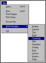
used in the Transformation module. APAS
Modules Selected to open additional APAS modules while keeping
the current program open. When this
command is selected, the user will be presented with a list of APAS modules. Exit Selected to EXIT the TRANSFORMATION program. EDIT COMMAND MENU
Copy Selected to Copy the currently selected items to the
Windows clipboard. This feature can
also be activated using the keyboard by simultaneously selecting the Ctrl and C
keys. VIEW COMMAND MENU
APAS
Toolbar Selected to toggle on/off the APAS toolbar.
When this option is active, the APAS toolbar will be displayed and allow
the user to select additional APAS modules while keeping the current program
open. The toolbar can be positioned
to the desired position by dragging it with the mouse. Status
Bar Selected to alternately display the status bar located
at the bottom of the TRANSFORMATION window.
The check mark indicates that the Status Bar will be visible. Switch Selected to alternately Switch between the View
Information grid and the Stick figure displays. 2D/3D COMMAND MENU
DLTs
etc... Selected to display the Direct Linear Transformation (DLT)
and/or Physical Parameter Transformation (PPT) transformation parameters for
each view. Transform Selected to Transform the selected views into
3-dimensional image space. Stop Selected to Stop the Transformation process prior to
completion. SYNCH COMMAND MENU
AutoSynch Selected to Automatically Synchronize the selected
views using the Synchronize algorithm. Reset Selected to remove any synchronizing information added
by the AutoSynch command. This
command will return the sequence to the original condition. OPTIONS COMMAND MENU
Options Selected to set various program options.
When this command is selected, a new menu will be displayed on the
screen. Select the MISC tab
to indicate if the Physical Parameter Transformation (PPT) algorithm should be
used. NOTE:
The PPT algorithm is required for Panning camera views. It is
optional for stationary camera views. Select
the UV tab to specify the color of the stick figure diagram for each of
the digitized views. Select the XYZ
tab to specify the color of the transformed �stick-figure� image.
Select the SMOOTH tab to activate/de-activate the automatic
smoothing parameters. HELP COMMAND MENU
Index Selected to provide an INDEX of Help related topics. Using
Help Selected to provide instructions on using the Help
Windows. About
TRANSFORMATION (C3D) Provides program information, version number and
copyright for the TRANSFORMATION program. [Go to Lesson 4] [Go to Index]
|
|
Prepared by Gideon Ariel, Ph.D. www.arielnet.com |