|
|
Description |
[FrontPage Include Component] |
|
|
|
|
|
|||||
|
|
|||||
| |||||||||||||||||||
|
Description
Categories
|
Description - Ariel Performance Analysis SystemAPAS is the most advanced computer-based system for the measurement, analysis, and presentation of movement performance.
Since 1971, the Ariel Performance Analysis System has assisted medical professionals, sport scientists, and athletes to understand and analyze movement using its advanced video and computer motion measurement technology. It surpasses all other video systems for quantitative accuracy and scientific excellence for the most cost effective choice in major medical and research institutions around the world.
3dkin - 3D kinematics and kinetics
3Dkin program introduces a new approach for calculating joint center. Estimating 3D kinetics of the lower extremity the joint center of the ankle, knee and the hip must be obtained. The previous approach has been the use of anthropometric data which covers relative location of the joint center with respect to an arbitrary coordinate system created using three well defined/positioned markers. In order to compensate for individual variation in joint structure the joint centers are digitized for the first few frames of the sequence of interest. 3DKin calculates the actual parameters for estimating the joint centers for the individual in question. This approach will also cover for some of the variation in the position of the markers. Analog - measurement and analysis subsystem
The module is designed to sample, save and present analog signals from many independent channels. A fast measurement rate is possible, with high resolution and programmable input voltage ranges. Data signals are measured to a 12 bit (1 in 4096) resolution. A number of triggering options are provided to assist in the capture of transient data and to allow the synchronization of the analog module with external events. The analog module also includes a set of specialized EMG signal processing options. EMG data samples can be analyzed using a number of sophisticated techniques including spike analysis, signal rectification and integration, envelope processing and spectral analysis. Capture - transfer of analog video to disk
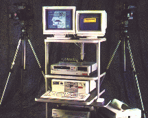
The Capture program is designed for capturing analog video and requires the analog frame grabbing hardware. This module does not support using the Digital Video (DV) capture hardware, for which a separate module is available. Digitize - automated or computer-assisted video analysis
Manual digitizing is performed under computer control and the digitizing of video images is computer assisted. A trained operator with a reasonable knowledge of anatomy and a consistent pattern of digitizing can rapidly produce high-quality digitized images. Automatic digitizing requires some sort of visible markers. User input is minimal as the computer automatically tracks the markers based on color, contrast, position, velocity and acceleration. Display - complete presentation for biomechanical analysis
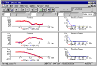
Display
allows simultaneous presentation of the three-dimensional stick figures,
displacement, velocity, acceleration, video images and numerical data tables as
well as analog data signals. The
stick figures may be displayed in single frame, multiple frames or animation
mode with multiple image sequences being viewed at the same time.
The size, location and orientation of the stick figures for each sequence
can be set in any manner desired to create comparison displays.
Text labels can be added to the display to create complete illustrations
and copies of the color graphic display may be printed from the color printer. The
software also allows normalizing the data signals in both time and amplitude. EMG - electromyography data collection and analysis
Electromyography is the study of muscle activity by measuring these electrical signals. Clinicians and researchers have applied the study of EMG to the fields of neurology, surgical assessments, functional capacity evaluations, ergonomics and overuse injuries, and chronic pain evaluations, just to name a few. In addition to the extensive EMG analysis options found in the Analog module of the Ariel Performance Analysis System (APAS), the Ariel EMG program provides additional capabilities. The EMG module is a Windows based program for calculating the integral and normalizing the EMG signal in both time and amplitude. An understanding of the electrophysiology and the technology of recording is recommended for optimal use of the EMG program. Filter - smoothing and filtering of random noise
The digitizing process involves measuring the location of each body joint. As with any type of measurement, there is no correct value, only an estimate to some known level of accuracy. Therefore, each measurement consists of two parts: the actual or true value, plus an error value due to the inability to perform exact measurements. This module will improve digitized joint locations by minimizing the effect of the errors made during the analysis process. In addition to the displacement curves, it can display velocity and acceleration curves for each component. By viewing the acceleration curves, the extent of random error remaining in the data can more easily be determined. Gait - gait analysis and rendering system
APAS/Gait uses 3-dimensional rendering of the kinematic data in real-time. This allows you to visually validate anything you are doing. If you inadvertently input a wrong anthropometric measure, or if your data contains errors of any kind, you will be able to spot this immediately in the 3D display. Realcap - transfer of analog video to disk
RealCap (Real time capturing) uses a new and improved technology to provide real-time video capturing with the PC. The software and the associated hardware removes the use of expensive VCR equipment using advanced field by field stepping. This allows 60hz video capturing from any video camera, and allows capturing in any speed when high speed cameras are used in conjunction with compatible VCR. As long as any high speed camera enable to store data in NTSC or PAL, the RealCap is compatible. RealCap is an easy to use module that can make use of external computer controlled VCR equipment synchronizing the video capturing process. Renderer - real-time rendering of kinematic data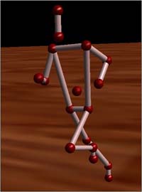 APAS 3D Renderer is an add-on
module to the APAS System that lets you render
3-dimensional kinematic data in real-time. We strongly believe this module is a valuable addition to standard
"stick figure" displays because rendered 3D models can convey
more information about segment orientations than stick figures.
APAS 3D Renderer is an add-on
module to the APAS System that lets you render
3-dimensional kinematic data in real-time. We strongly believe this module is a valuable addition to standard
"stick figure" displays because rendered 3D models can convey
more information about segment orientations than stick figures.
Although rendering 3D kinematic data is generally a task that is not easily undertaken by many of us, we strongly believe we have succeeded in creating a product that is easy to use and gives impressive and smooth rendering results on inexpensive hardware. Transform - compute 3D kinematic data based on video analysis
Transformation is the process of converting two or more, two-dimensional digitized views into a three-dimensional image sequence. The transformation option is also available to convert a single, two-dimensional digitized view into a two-dimensional image sequence. In either case, the process involves transforming the relative digitized coordinates of each point in each frame to absolute image space coordinates. This process is performed entirely by the computer. Some initial timing information will be requested, after which the transformation will occur automatically. Trim - synchronize different video views
The Trim module is a Windows based program that
provides the ability to edit several video sequences simultaneously. The video editing phase
of analysis is performed after all camera views have been captured to the
computer but prior to being digitized. The
purpose of this phase is to clip the stored AVI file from each camera view based
on the synchronizing event. Trimming
is the process of �cutting-out�
a series of images in the captured video file into a more manageable segment that
can be used for analysis. Vectors - visualize ground reaction forces
It is often valuable to combine the ground reaction force with the video data. The Vectors module is a Windows based program for superimposing the 3-dimensional ground reaction force vector onto an AVI video image using the Ariel Performance Analysis System (APAS). Specialized laboratories study these vectors with the goal of improving sports performance, evaluating injuries or the effects of disease. The Vectors module provides the clinician with the tool to observe any deviations between normal leg and foot alignments with the resultant force vector. View - complete presentation for biomechanical analysis
With the Data Window you can display almost any kind of numerical data collected over time. For example velocity, acceleration, height of center of gravity, joint moments, EMG, and so forth. The AVI Window features the display of video (AVI files) together with force plate vectors and stick figures. The Stick Window is designed for displaying force plate vectors and marker trajectories as stick figures using APAS .3D files as data source. The two types of data can be displayed together or separate. |
|
|

 The
study of the motion of living things is known as "Biomechanics" and it
has evolved from a fusion of the classic disciplines of anatomy, physiology,
physics, and engineering. Biomechanical quantification are based on Newtonian
equations and the APAS analytic technique models the human body as a mechanical
system of moving segments upon which muscular, gravitational, inertial, and
reaction forces are applied. Although the system has primarily been used for
quantification of human activities, it has had some industrial, non-human
applications. The computerized hardware/software technique provides a means to
objectively quantify the dynamic components of movement and replaces mere
observation and supposition.
The
study of the motion of living things is known as "Biomechanics" and it
has evolved from a fusion of the classic disciplines of anatomy, physiology,
physics, and engineering. Biomechanical quantification are based on Newtonian
equations and the APAS analytic technique models the human body as a mechanical
system of moving segments upon which muscular, gravitational, inertial, and
reaction forces are applied. Although the system has primarily been used for
quantification of human activities, it has had some industrial, non-human
applications. The computerized hardware/software technique provides a means to
objectively quantify the dynamic components of movement and replaces mere
observation and supposition. 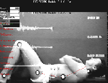 Ariel
Dynamics Inc. invented the first computerized Movement Analysis System, known as
the Ariel Performance Analysis System (APAS) in 1968. The System's inventor, Dr.
Gideon Ariel, developed the first online electronic digitizing system for
reducing each picture in a film sequence, and later from a video, into its
kinematic components.
Ariel
Dynamics Inc. invented the first computerized Movement Analysis System, known as
the Ariel Performance Analysis System (APAS) in 1968. The System's inventor, Dr.
Gideon Ariel, developed the first online electronic digitizing system for
reducing each picture in a film sequence, and later from a video, into its
kinematic components.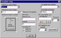 3Dkin is a program for calculation of
human lower extremity kinematics and kinetics in 3D. The convention is based on a
anatomical coordinate system providing information on joint flexion/extension,
abduction/adduction and also internal/external rotation. The mathematical model for the
kinetic calculations is based on inverse dynamics using a free body diagram.
3Dkin is a program for calculation of
human lower extremity kinematics and kinetics in 3D. The convention is based on a
anatomical coordinate system providing information on joint flexion/extension,
abduction/adduction and also internal/external rotation. The mathematical model for the
kinetic calculations is based on inverse dynamics using a free body diagram.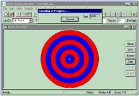 The Analog module is
used as a general purpose laboratory data measurement and analysis sub-system.
The Analog module is
used as a general purpose laboratory data measurement and analysis sub-system. 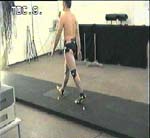 The first analytic step after recording
is transferring the video image into the computer hard disk for digitizing. The
Capture module is a Windows based program for capturing and storing these images for
analysis using the Ariel Performance Analysis System (APAS).
The first analytic step after recording
is transferring the video image into the computer hard disk for digitizing. The
Capture module is a Windows based program for capturing and storing these images for
analysis using the Ariel Performance Analysis System (APAS).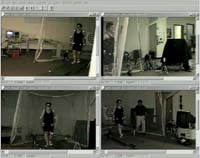 Digitizing is the first step
for analysis after the recorded images have been captured and stored on the hard disk of
the computer. The Digitize module is a Windows based
program for digitizing images to be analyzed using the Ariel Performance Analysis System
(APAS). Digitizing can be performed in one of two modes, either Manual or Automatic.
Digitizing is the first step
for analysis after the recorded images have been captured and stored on the hard disk of
the computer. The Digitize module is a Windows based
program for digitizing images to be analyzed using the Ariel Performance Analysis System
(APAS). Digitizing can be performed in one of two modes, either Manual or Automatic. 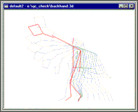 Once an analysis sequence has been digitized,
transformed and smoothed, the Display module can be used to
obtain a complete presentation of image motion data for biomechanical analysis.
Once an analysis sequence has been digitized,
transformed and smoothed, the Display module can be used to
obtain a complete presentation of image motion data for biomechanical analysis.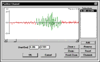 One of the most intriguing and
challenging areas of study in biomechanics is probably the muscle itself. The electrical
signal associated with the contraction of a muscle is called an electromyogram or, by its
shorthand name, EMG.
One of the most intriguing and
challenging areas of study in biomechanics is probably the muscle itself. The electrical
signal associated with the contraction of a muscle is called an electromyogram or, by its
shorthand name, EMG.
 Filter
is used
to remove small random digitizing errors or "noise" from the transformed image
sequence.
Filter
is used
to remove small random digitizing errors or "noise" from the transformed image
sequence.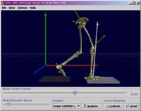 APAS/Gait is an add-on module to the
APAS
System. It allows full-fledged gait analyses using industry-standard
marker sets. It will generate standard charts and standard analysis
reports with a click of a button.
APAS/Gait is an add-on module to the
APAS
System. It allows full-fledged gait analyses using industry-standard
marker sets. It will generate standard charts and standard analysis
reports with a click of a button. 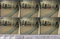 Capturing a video sequence
utilizing the full speed provided with today's video standard (50Hz in Pal and 60Hz in
NTSC) it is normally required to use special VCR equipment with field by field stepping
capabilities. Using RealCap it is possible to capture video sequences from a
VCR or camcorder directly to the computer hard drive without special requirement of
expensive VCR equipment.
Capturing a video sequence
utilizing the full speed provided with today's video standard (50Hz in Pal and 60Hz in
NTSC) it is normally required to use special VCR equipment with field by field stepping
capabilities. Using RealCap it is possible to capture video sequences from a
VCR or camcorder directly to the computer hard drive without special requirement of
expensive VCR equipment.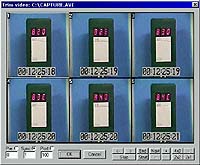 When video images are
captured directly from the camera to the hard disk drive on the computer, it is
common to capture more images than are required for the desired analysis.
When video images are
captured directly from the camera to the hard disk drive on the computer, it is
common to capture more images than are required for the desired analysis. One of the most common forces
acting on the body is the ground reaction force, which acts on the foot during standing,
walking or running. This force vector is three dimensional, consisting of two shear
components (X and Y) acting parallel to the ground plus a vertical supporting force (Z).
These forces can be measured using a multi-component force transducer. This transducer is
commonly know as a force platform. The force platform also provides the location of the
center of pressure of this ground reaction vector using the relative vertical forces seen
at each of the transducers.
One of the most common forces
acting on the body is the ground reaction force, which acts on the foot during standing,
walking or running. This force vector is three dimensional, consisting of two shear
components (X and Y) acting parallel to the ground plus a vertical supporting force (Z).
These forces can be measured using a multi-component force transducer. This transducer is
commonly know as a force platform. The force platform also provides the location of the
center of pressure of this ground reaction vector using the relative vertical forces seen
at each of the transducers.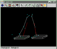 APAS/View is developed for dynamically
viewing stick figures, numerical data, force plate vectors and AVI videos. With
APAS/View it
is possible to load all data into the computer and display and evaluate multiple data sets
in multiple windows.
APAS/View is developed for dynamically
viewing stick figures, numerical data, force plate vectors and AVI videos. With
APAS/View it
is possible to load all data into the computer and display and evaluate multiple data sets
in multiple windows.