User's Guide
See also: point names
Screen Layout
Prior to beginning the Rendering process, you should familiarize yourself with the screen layouts of the various
menus. Many functions can be selected using the Renderer control panel or by selecting the appropriate command from the Pull-Down Menus.
Main Renderer Window

Control Panel
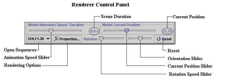
The Renderer Control Panel is used to adjust the 3D model display
parameters.
-
Open Sequences - Displays a list of the active models.
-
Animation Speed Slider - The speed/duration slider allows the user to control the speed of the animation.
-
Rendering Options - Selected to examine or modify the properties of
the active model. Properties include segment type, rendering options,
colors and translating options.
-
Scene Duration - The amount of time for the model to be displayed from
the first to the last image.
-
Rotation Speed Slider - The rotation speed slider allows the user to
adjust the rate of the scene rotation.
-
Current Position Slider - The position slider allows the user to go to any position (time really) in the animation.
-
Current Position - Displays the current position in percentage
of the entire sequence.
-
Orientation Slider - The orientation slider allows the user to rotate
the model about the Y (vertical) axis of the global coordinate system.
-
Reset - The reset button is selected to remove all orientations
performed by the mouse.
Starting the Renderer Program
Once the Java plug-ins have been successfully installed, the Renderer program
is started by double-clicking on the 3D-Render icon located in the APAS System
folder. This will open the main 3D Renderer window.
Opening a Model
The following steps are recommended for correct operation of the Renderer
program.
- Select the OPEN command from the FILE menu. The OPEN File Dialog box will appear.

The OPEN File Dialog box looks for a particular type of file (files that have the extension of (*.3D). This file is automatically created when a Sequence file is transformed using
the ARIEL TRANSFORMATION software module. The OPEN File Dialog box can be used to specify the Drive, Directory, and Name of the sequence file to be retrieved. Select the sequence name to be
modeled and then select OPEN to proceed. When the desired sequence is opened,
the rendered data figure will appear on the graphic display.
- Select the ADD ANOTHER command from the FILE menu to open
additional sequences.
Point Names
The program will attempt to fit bone geometry to your data.
The model assumes that the following points are present:
R.FOOT, R.ANKLE, R.KNEE, R.HIP, L.HIP, L.KNEE, L.ANKLE, L.FOOT,
R.WRIST, R.ELBOW, R.SHOULDER, L.SHOULDER, L.ELBOW, L.WRIST, CHIN, FOREHEAD.
If any of the above points are missing, your data will be
shown as cylinders. Future versions of this program may allow custom modelling.
Model Properties
The properties for each model can be adjusted independently. User
adjustable properties include segment selection, rendering options, segment and
point colors, trace options and also the ability to translate the model on the
graphic display.
Properties are adjusted using the following steps.
- Select the desired model from the list of open sequences in the lower left
corner of the control panel.
- Select the Properties button on the control panel. The Properties
menu will be displayed in a new window.
- Select the 3D Model tab to display the current model properties. The
name of the model will be displayed in the upper portion of the Property
menu.
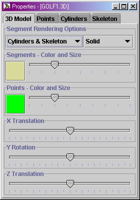
Segment Rendering Options - Selected to display the model segments as either
Bones or Cylinders.
Rendering Options - Selected to display the segments as Solid, Wire
Frame or Points Only.
Segment/Point Color - Selected to change the color of the model
segment/points.
Segment/Point Size Slider - Used to adjust the size of the
model segment/points.
Position Sliders - Used to translate the model along the global
coordinate system axes. This is often useful when multiple models are
simultaneously displayed.
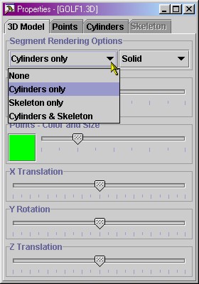
The segment rendering options control the way the model is
rendered. Choose from the given options (None, Cylinders only, Skeleton only,
or Cylinders & Skeleton). This choice may enable or disable some of the
other tabs. After opening the demo file GOLF1.3D, the default "Segment
Rendering Options" will be set to "Cylinders only"
("Properties", see screen shot below). I made this choice only
because of rendering speed (cylinders render faster than bones). Because
"Cylinders only" has been selected, the "Skeleton Tab" is
disabled (grayed). Change the "Segment Rendering Options" to
"Cylinders and Skeleton". This allows you to see both cylinders AND
bones. When doing this, the "Skeleton Tab" will be enabled too.
-
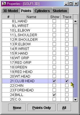
- In the "Points Tab" you can now indicate which
points you want to see, and also which points you want to trace. This is
to stress a certain point to the audience. For example, click the
"None" button below to disable everything, and then show the
CLUB HEAD and BALL points. The other points really convey no additional
information. You can use the sliders on the first tab to change the size
of the segments (to what you like) or the balls (a soccer ball is bigger
than a golf ball).
-
-
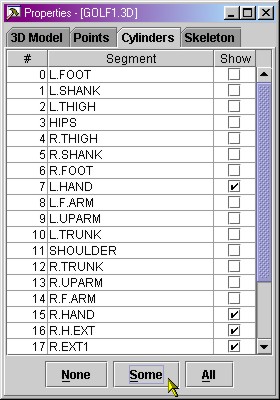
On the Cylinders tab, you can select which cylinders are
rendered. Choose NONE or ALL to deselect or select all cylinders at once. Or
select SOME to only select those cylinders which are not contained in the
skeleton (this option is only available when "Cylinders &
Skeleton" has been chosen in the Segment Rendering Options. On the
"Cylinders Tab" press the "Some" button. This will
enable all cylinders that are not contained in the skeleton. You can disable
and enable any cylinder you like here. Note that the
cylinders grow and shrink if the segment length is not constant. In previous
versions of the renderer, the segments became disconnected (not anymore).
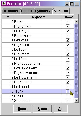
In the "Skeleton Tab" you can enable/disable any
available segment of the skeleton. If you choose "Some" it will
enable all bones, except for hands, trunk and head. Disabling the trunk and
the head (and perhaps hands) will significantly improve rendering speed
(especially the trunk has very complex geometry and takes extra time to
render).
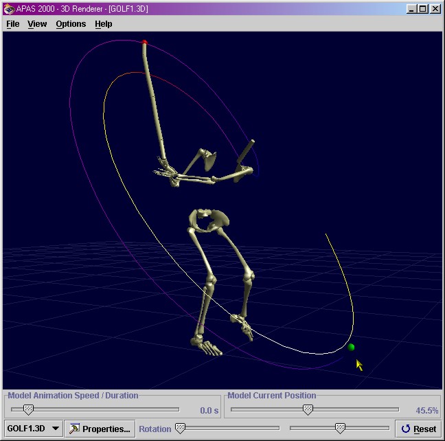
- If you selected all the above options, the resulting golfer
should look something like below. It's a good trade-off between rendering
speed and a nice-looking model. Notice that it has a combination of certain
points (club head and ball), certain traces (club head), certain cylinders
(club and head) and certain bones (all except trunk and head).
-
NOTE: Traces are displayed in multiple colors. These
colors indicate relative velocity. Darker colors indicate slowest
velocity while lighter colors indicate faster velocities.
Examining the scene
You can think of the scene as holding an object in your hands, for example a
pen. When examining a pen you can turn it around in any orientation: you
generally do not change your head orientation while examining a pen, but rather
you rotate and translate the pen with your fingers to examine it. APAS 3D Renderer uses a similar mechanism to examine a scene.
The 3D model scene can be rotated and/or translated using the options listed
below.
Changing Orientation
By default, the 3D model scene opens and displays the sequence in the XY
plane (as defined by the control points in the APAS Digitizing module).
The displayed orientation can be changed using the mouse or slider bars.
Mouse Button Functions
Using the mouse
you can change the location and orientation of the scene in a virtual
universe.
The software uses
interpolation between the different frames to achieve the smoothest possible
animation on your hardware.
An example: Suppose you play a 2-second sequence containing 100
frames, captured using a PAL system at 50 frames per second. When rendering
this animation and setting the total length of the animation to 60 seconds, you
would normally achieve a frame rate of about 100/60 = 1.67 frames per second.
But 3D Renderer uses a different strategy: if your hardware allows you to
achieve a full 50 frames per second, the software will automatically interpolate all
segment orientations: it will calculate 60 * 50 = 3000 new orientations for each
segment: this effect is immediately noticeable to the user. Instead of watching
the animation play at a jerky 1.67 frames per second while wasting your system's
CPU-time, you will be able to exploit your hardware to the fullest and examine your
animations in super-slow-motion at a 50 frames per second frame rate.
Renderer Quick Reference
Opening A Model