|
|
Lab Settings |
[FrontPage Include Component] |
|
|
|
|
|
|||||
|
NAVIGATOR: Back - Home > Adi > Services > Support > Tutorials > Gait : |
|||||
|
|
|||||
| |||||||||||||||||||
|
Lab Settings
Categories
|
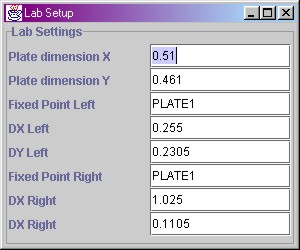
Lab Settings - Force Plate SetupCheck also our tutorial for general information on gait lab setup. Or this interactive lab. APAS/Gait can correlate force plate data with kinematic data in 3D space. For this you need to supply the program with your plate dimensions, and where your plates are relative to the kinematics reference frame. It's easiest to understand this by looking at the following example. The values here are the values used in our lab:
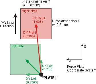
All values are in the "force plate coordinate system" (which means positive X in the subject's walking direction, and positive Y perpendicular to X towards the left). As you can see in our setup, our plate dimensions are 0.51 x 0.461 m. The other settings identify the plate centers relative to a fixed marker (which is identified in our kinematics files as a fixed point called PLATE1). In our lab, the left plate center is at (0.255, 0.2305) relative to marker PLATE1. The right plate center is at (1.025, 0.1105) relative to the same marker PLATE1. Note that these values are in the plate coordinate system. Note that it is also possible to use a second marker to identify the second force plate (for example called PLATE2), but we cannot really think of a reason to do so.
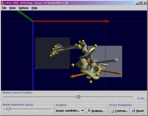
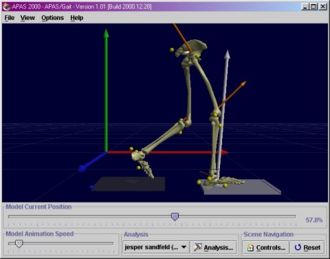
See the screen shots below to see our lab settings in 3D space. To better understand these settings, we invite you to explore them in APAS/Gait or in this applet. It will give you a better feeling for the location of the force plates in 3D space. The blue ball represents the marker called PLATE1 and is the marker fixed on the right corner of the left plate (plate 1). This fixed marker PLATE1 should be digitized and thus be present in all kinematic data files (*.3D). Note that the fixed marker PLATE1 does not have to be in the "origin" of the lab (as defined by the calibration cube in the kinematics file). The origin of the lab (= global coordinate system) is represented by the point where the triad of vectors meet (X, Y, Z).
|
|
|